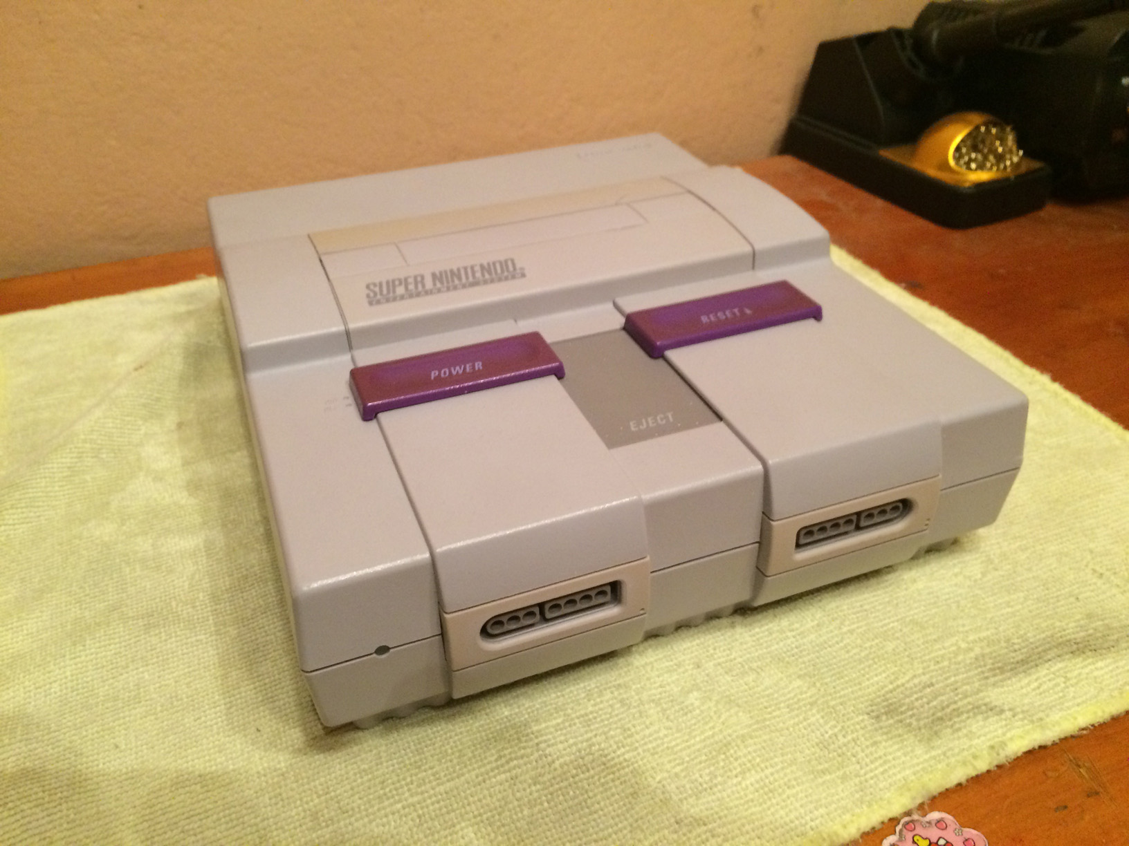
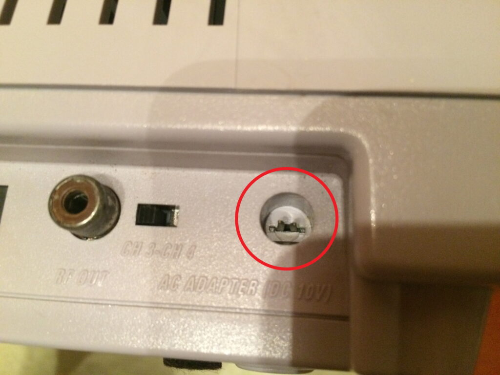
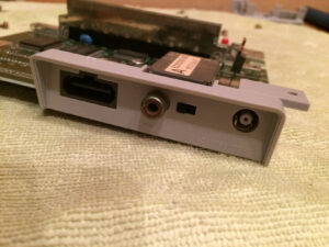
Recently, I purchased an old Super Nintendo console system -SNES as commonly referred- to get some retro gaming action on. To my surprise, after hooking it up, I discovered that the power connector was broken, which prevented the power cable to supply the energy in a reliable way, sometimes the console wouldn’t even start.
Instead of returning it, and probably get a yellower replacement, I decided to open it up and repair it!
So, without further ado…
Tools
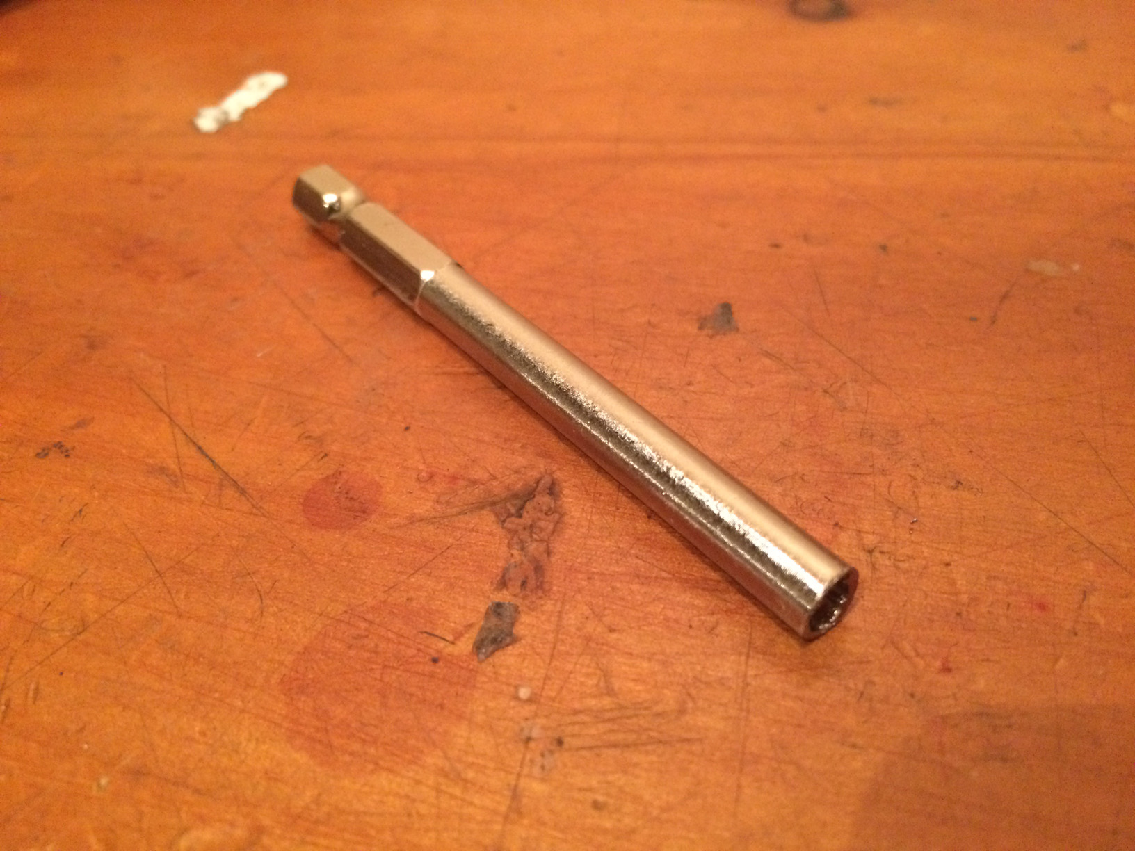
- Weird SNES screw driver/bit. It has special tip to remove SNES screws, aka Security Screwdrivers (I got if from ebay)
Soldering iron, solder.
- Phillips screwdriver.
- De-soldering tool.
Parts
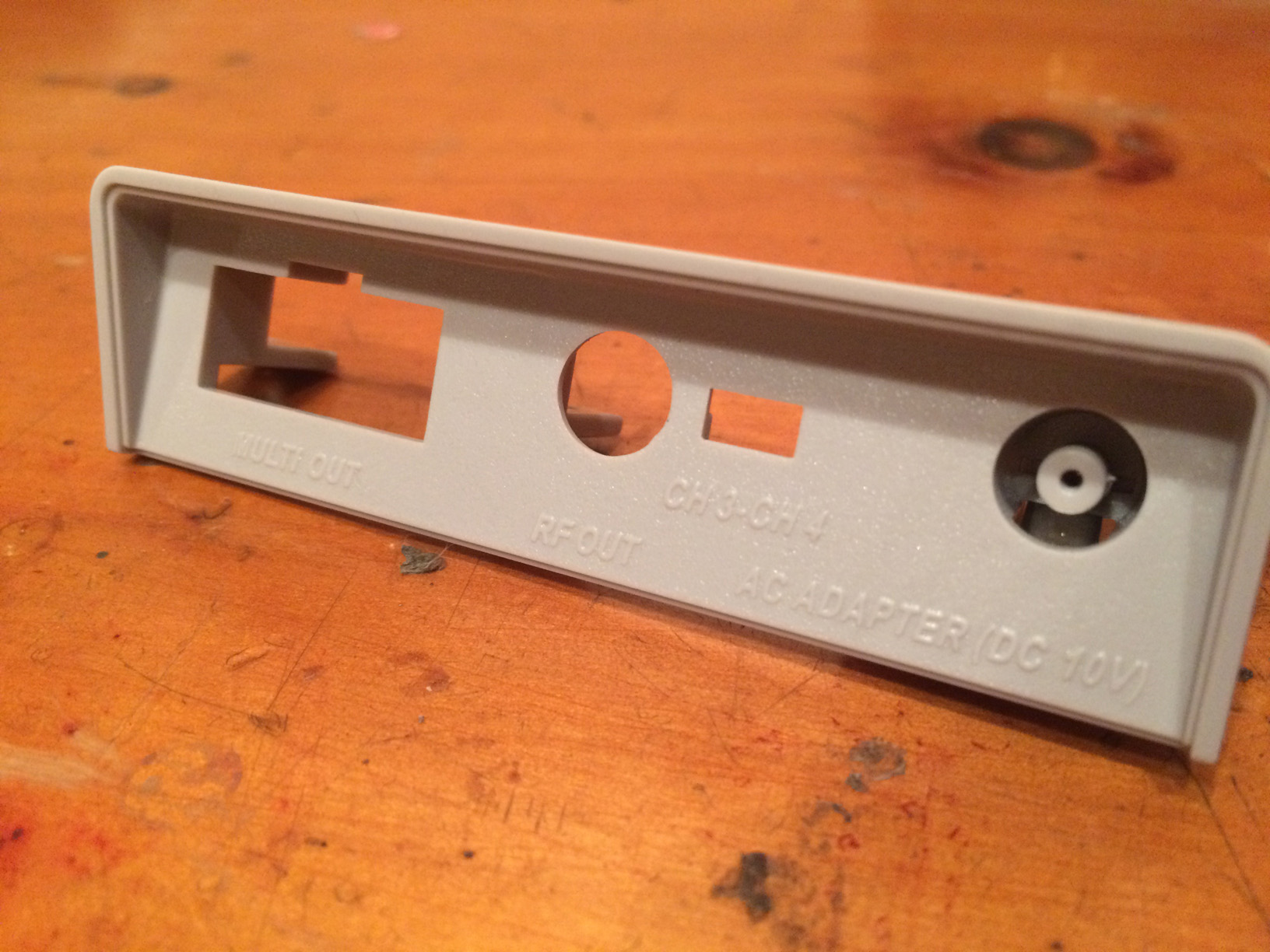
- SNES back panel replacement. (I got mine from ebay)
Steps
(Click on any image to see it bigger!)
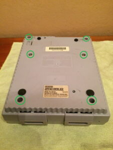
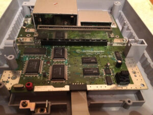
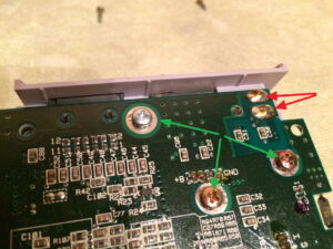
Turn the SNES over, remove the screws in the circles.
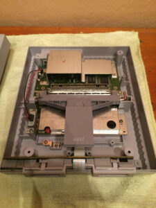
You will then have the following view:
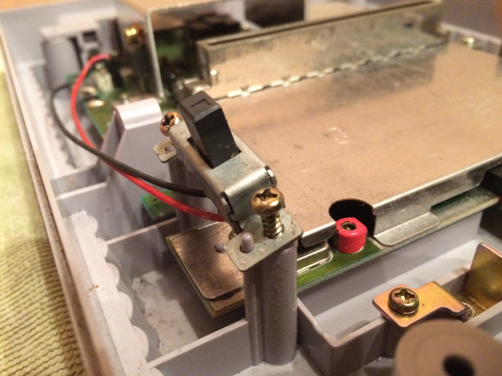
Remove the power switch, held by two screws:
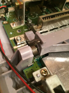
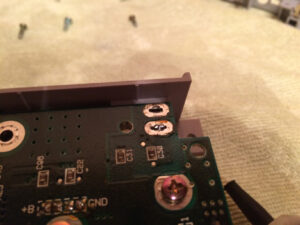
Carefully remove the following spring, take note of its position, you will have to put it back as it was, this action will allow you to remove the cartridge eject mechanism on the SNES.
You’ll have this view after its removed:
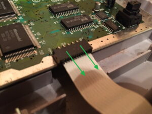
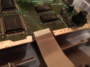
Carefully remove away the ribbon cable connecting the SNES ports to the main board, following the direction pointed by the green arrows.
Depending if your cartridge connector is removable or not, remove it from the board by pulling it out. If you have one replacement, you can swap it for the new one here and assemble back the SNES.
Also, now you can remove the motherboard from the plastic housing.
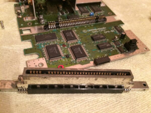
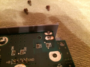
Once that is done, turn the board face down, and remove the green marked screws taking special note on where they were located. Use your soldering iron and desoldering tool to remove the red marked solder points.
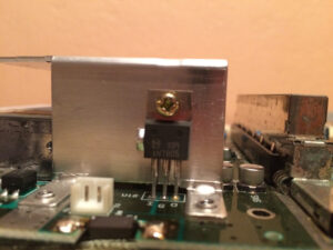
Turn the board around remove all screws holding the big aluminum heat sink. Including the screw holding the voltage regulator. Don’t forget this one to avoid damaging the regulator.
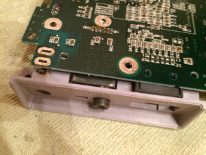
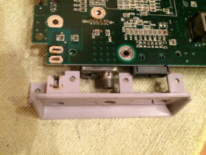
Without it you will be able to remove the last 2 screws holding the plastic assembly in place (no photo taken). Once you remove them turn the board around, with the ports facing you and start pulling the plastic away from the motherboard. It would take some effort to do as the metallic pins of the jack will get stuck in place, take note that the metallic pins are attached to the plastic as one piece. You can use a flat screwdriver to carefully lift the plastic so that the leads clear the holes of the motherboard.
I recommend rocking motion to safely move the plastic away from its position.
If you want to do it quicker, you can probably cut away the plastic with a rotary tool too, you will be replacing it anyways.
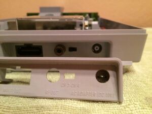
Once you are done you’ll have the following view:
Replace with the new plastic assembly, solder it up in place.
Start putting everything back together backwards. You are done.
If you have any comment or question, ask away!
Leave a Reply