
Today, the newest cars in the market ship with their own touch screen where you can visualize radio, navigation, etc. At the time, my car didn’t come with any of that. So, I set out in a quest of adding a screen to it, but not just any screen, I wanted a tablet, and the Nexus 7 was the perfect choice.
Perfect choice? For much as I love Apple and its cool devices, I knew that adding an iPad to the car would limit my possibilities. iOS is a cool operating system, but it can only do so many things. Any other capability that was not planned, you have to compromise. Off course we can jailbreak, but I prefer not to. Another reason would be the lack of GPS; If you want to use it you will have to get the pricier GSM model, since only that version supports it.
As you can see, this leaves us with the alternative, get a device with an open OS. This will help us later on the road with any customizations, we’ll get there later on (part 2). The choice at the time was the first Nexus 7 with 16GB of onboard storage, It was a pure Android experience, and the best of all it included a GSM radio on its Wifi model.
If you plan to buy one to perform this mod, I would rather pay a little more and get the GSM model, it will give you the advantage to get internet connectivity out-of-the-box, something I had to solve with an external hotspot.
The Result
The Process
The process was long, and I don’t remember everything anymore. I’ve been meaning to write this post since 2014, then I sold my car, and the tablet went along with it.
I will try to divide the process it in various parts, maybe I’ll remember more with if I put my mind into it.
The Navigation Screen
Parts:
- 12V to 5V DC-DC converter. Can be a fancy digital one or your trusty 7805
- Mazda Navigation Assembly for the year and model of your car (important).
- Arduino Pro Mini (or something smaller with same feature set)
- 1 BA6209 H-Bridge
- Misc electronic parts. (wires, connectors and such)
- Tablet (Nexus 7)
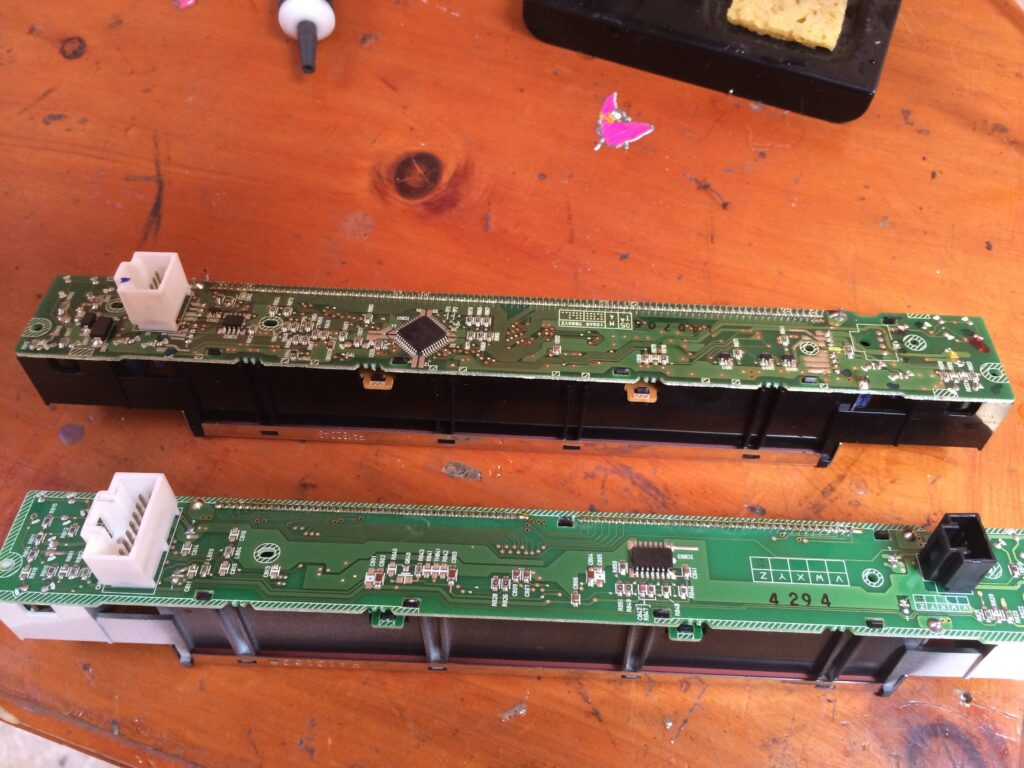
So, the main problem I faced during this project was that I could only get the Mazda Navigation Assembly for a 2005 model, and my car was a 2006 model, between these two years, Mazda decided to change the whole circuit board of the small secondary LCD screen. Meaning it was not just a matter of exchanging the two screens as I originally thought (often sold together). I needed to hack them together, by getting the front bezel from the 2005 version with the circuit board of the 2006 version. This proved more difficult than expected.
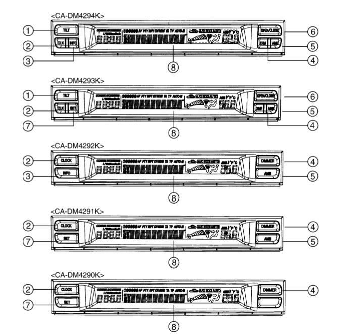
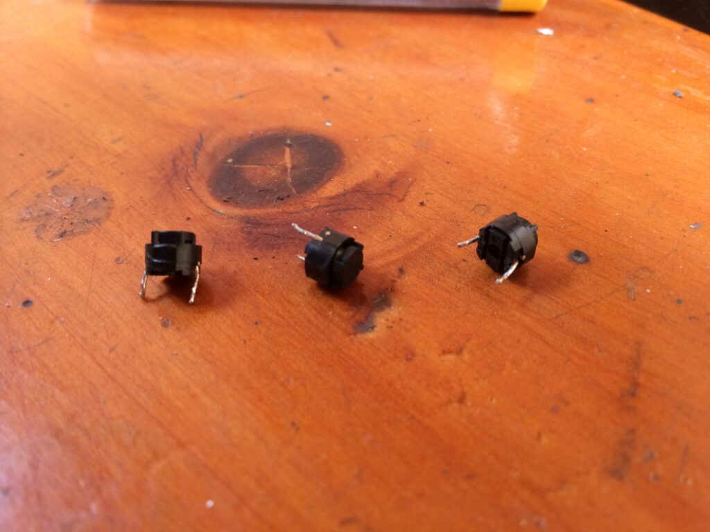
This would have been easy if it wasn’t for the fact that as a cost reduction strategy, Mazda decided that if you didn’t have a navigation screen then you would not need the buttons for it. So they designed like 5 different screens with different button configurations. As shown here.
The only redeeming factor here was that after the circuit board was the same. It only lacked the push buttons for each function and some resistor bridges were not made, those controlled the function of said buttons differently depending on what was shorting what.
Using the datasheets I was able to determine what was missing in my screen and used that information to convert my CA-DM4591AK into a CA-DM4593AK by using the parts from a CA-DM4294K… (If that doesn’t make any sense, just continue, and hope that you don’t have this problem)
The following link contains the datasheets for the LCD screen in case you do. I highly recommend getting the right screen for your model.
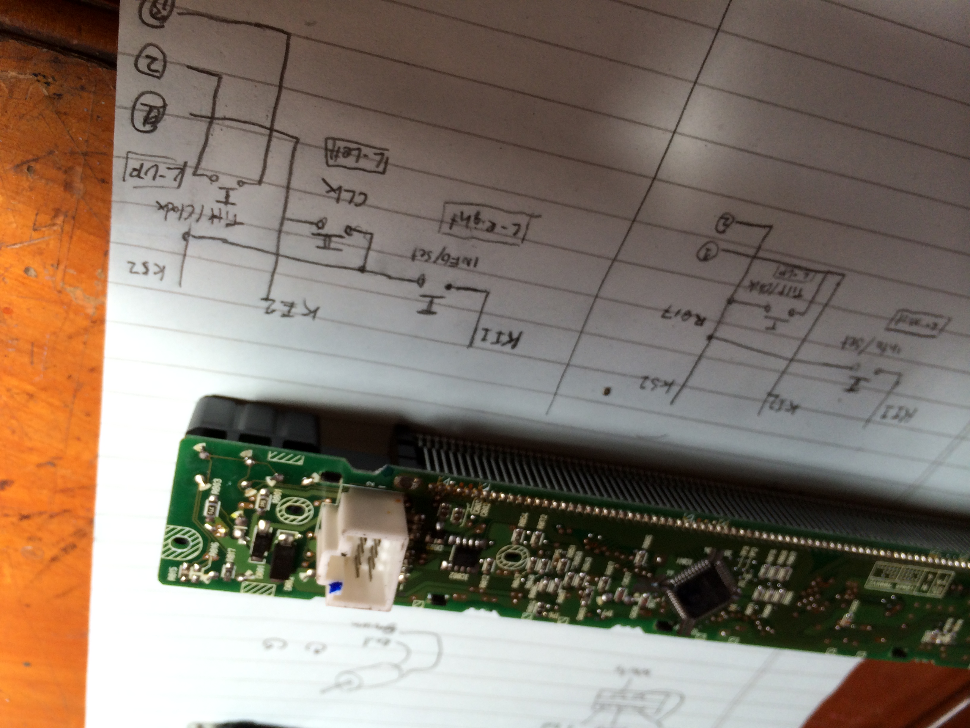
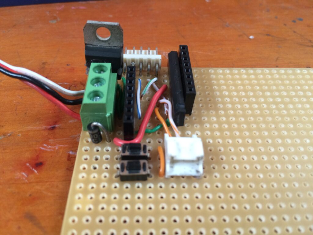
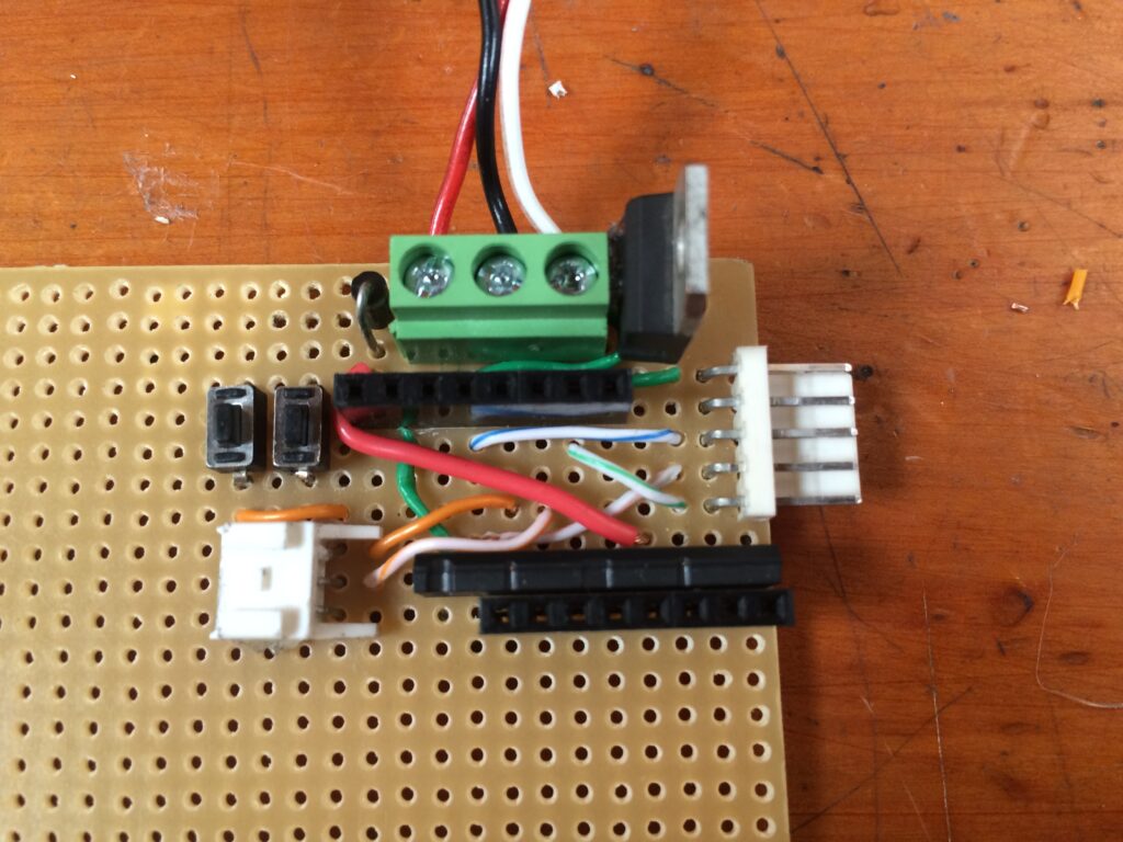
This photo “details” the circuit I followed to bridge the gap between these screens. I went from a two-button design to a three-button design.
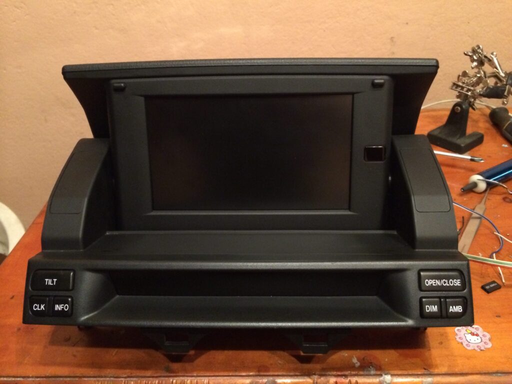
The Tablet
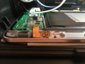
I affixed the tablet to the Navigation assembly using double sided tape. The tablet fits perfectly inside the assembly. But the screen opening in the assembly is smaller than the size of the tablet screen. This ended up hiding the whole bottom bar (where the home button is located). I had to use an alternative software method to have the buttons in the side (when the tablet is in landscape mode). I did not want to hack the assembly I was going for the “stock look” as much as possible, since I didn’t want the dashboard to look any different.
After assembly was complete, I ended up with a 2006 version assembly.
The Code
In order to run the assembly I had to create a little Arduino program to read the button presses from the Tilt and Open/Close button –which is available as a 3 pin header that goes out the secondary screen- and drive the motor using an H-Bridge and also read the relative location using the potentiometer attached to the gearing mechanism.
A pending feature is to implement interrupts, so that the Arduino would remain in sleep mode, until the buttons are pressed. This would save a lot of power. I was dumb and didn’t plan for that so my circuit didn’t use the interrupt enabled pins and it was too much of a pain to rewire it. So think about that when you build your own version.
Here is a link to the repo.
https://github.com/amd989/Navi
The Circuit
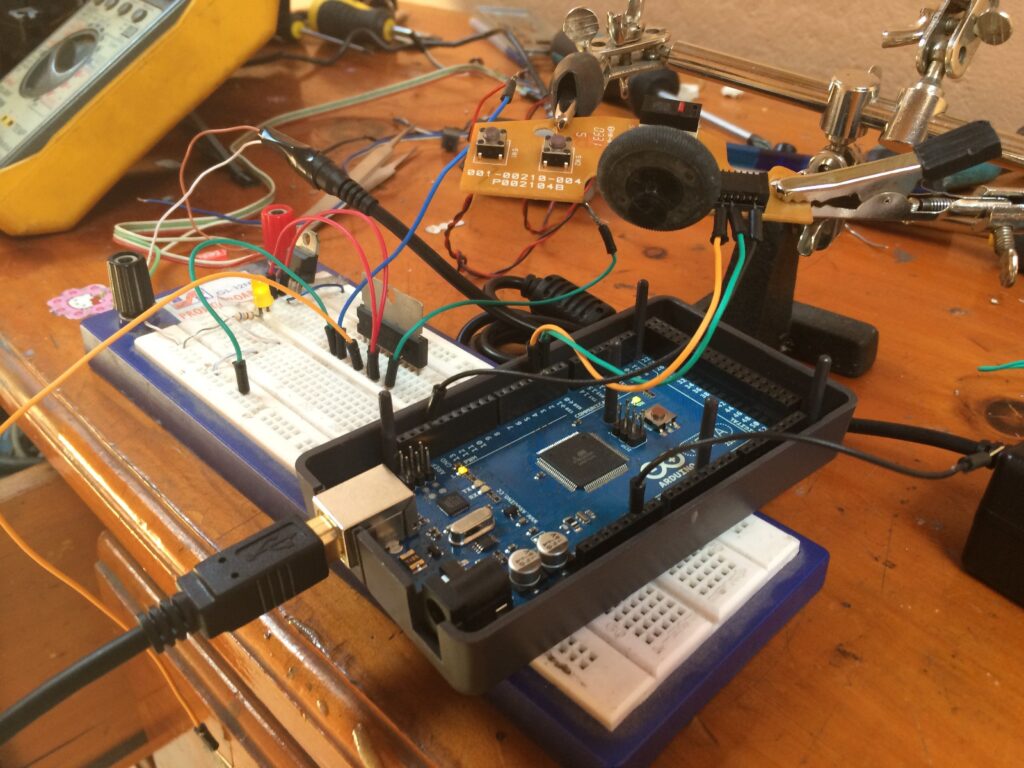
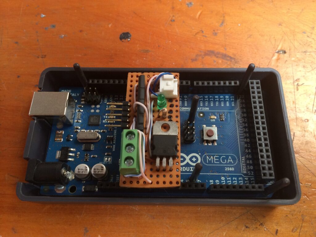
I started using an Arduino mega, but that proved to be really power hungry, so my car battery would die within three days if I didn’t drive the car enough, so I don’t recommend using one of those at all. It was clunky and made the whole solution bigger, and the uncertainty of being stranded didn’t help.
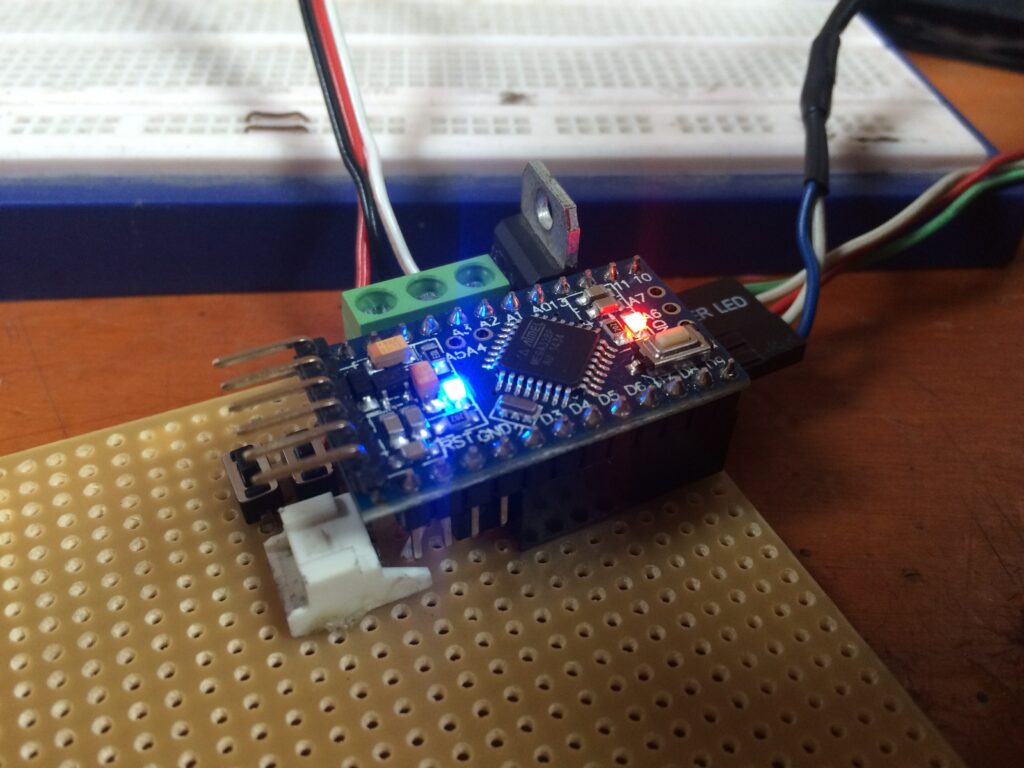
I later moved to an Arduino Pro mini, that proved to consume nothing in comparison and made the whole project a lot smaller. I also added two push buttons to the circuit board itself to aid in testing the tilt and open/close distances.
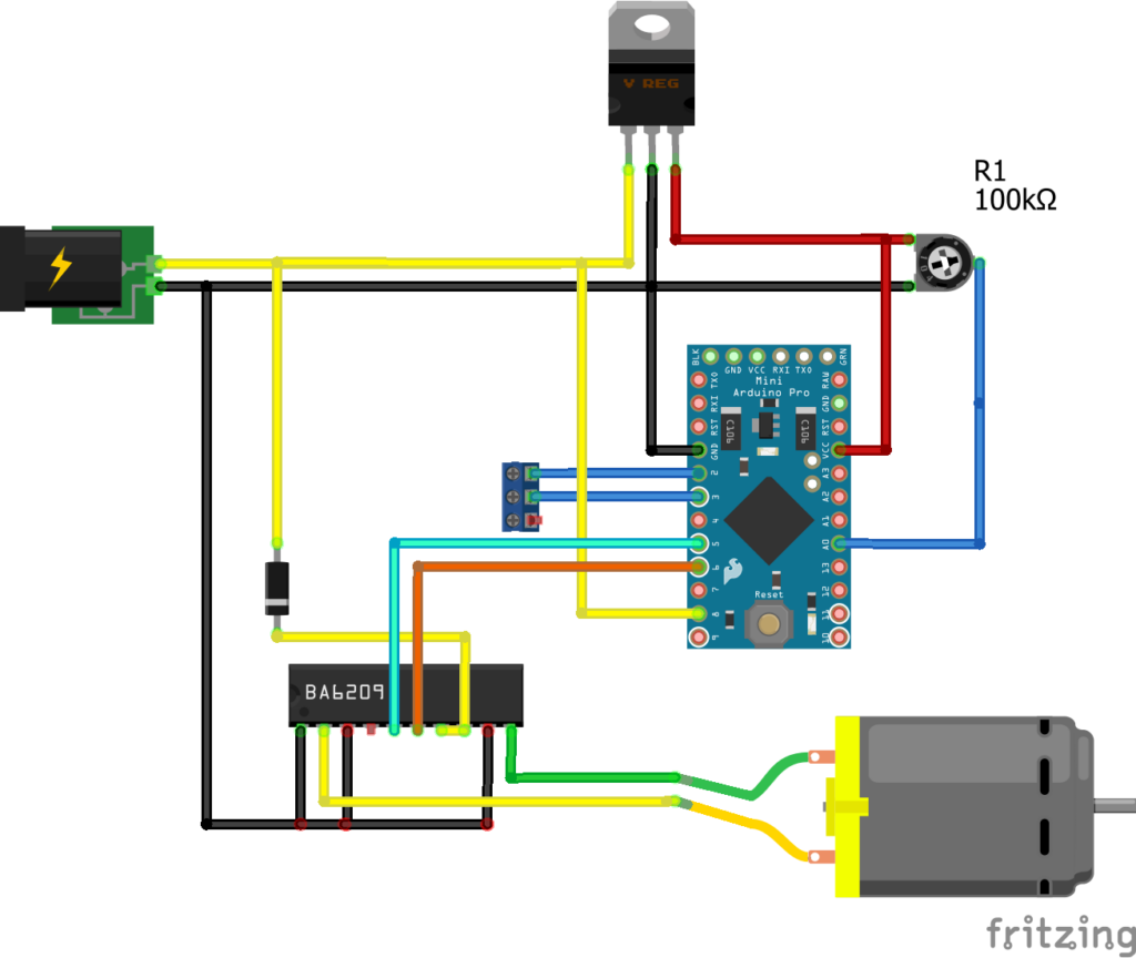
Schematic
Here is a rough schematic of how you are supposed to wire the display assembly. I don’t remember it correctly, but this is a close approximation.
MKI
MKII
Power button
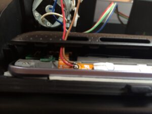
I also needed a way to access the power button of the tablet once everything was assembled, I ended up soldering the tablet’s power button into the DIM button (2006 Mazda 6 doesn’t use this feature anymore, so it meant that the button was available of something else) of the secondary LCD screen.
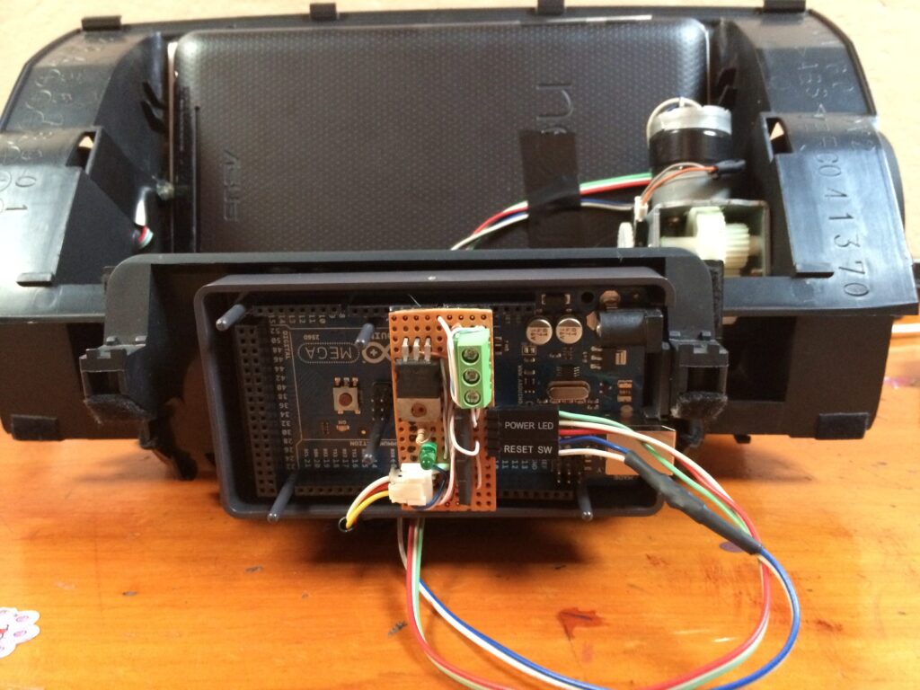
Testing the controller
That’s it.
I will update this post if I remember more… I can’t believe four years have passed since I finished this project. Talk about hating blogging.
Part 2 will probably deal with the software side in the tablet. Custom apps I used and such.
If you have any comment or question, just write it below.
Cheers.
Leave a Reply